
CNC Pipe Sizing Machine
CNC Pipe Sizing Machine Features
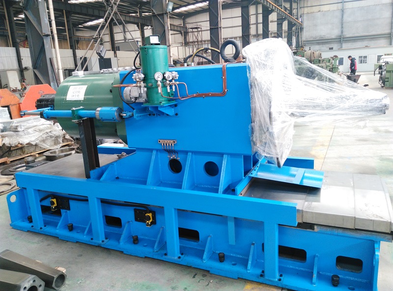
The basic principle of the equipment is to use the powerful cylinder tension to pull the tie rod, and the horizontal movement of the tie rod is transformed into the radial expansion movement of the expanding die (6 segements type) through the inclined block, to achieve the purpose of expanding the inner diameter of the steel pipe.
The newly designed tube body expanding mechanism reduces the number of molds and consumption.
The pipe end sizing machine production line is composed of two sizing hosts with the above (lower) material bench, stepping steel unit, lifting and rotating roller table, and other auxiliary machines and electrical control system, which can carry out continuous production with high efficiency.
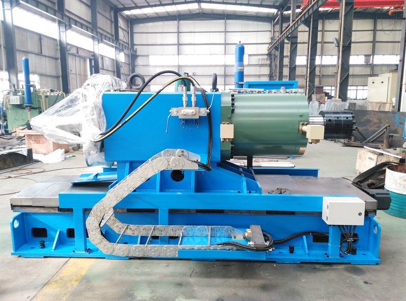
CNC Pipe Sizing Machine:
The pipe sizing machine is utilized to reshape the size of the pipe end through the use of shrink or expanding dies, which can enhance the yield of steel pipes in subsequent processing.
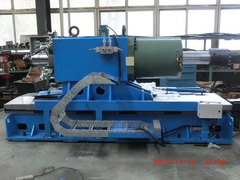
It consists of a base, a passive support roller, a clamping device, a floating beam, a main hydraulic cylinder device, a tension rod, and shrinking dies.
The passive support roller can be vertically driven by a hydraulic cylinder and is equipped with an electric limiting device. There are two sets of clamping devices that are driven by hydraulic cylinders to firmly clamp the steel pipe.
The hydraulic system is equipped with pressure adjustment and detection devices that allow for adjusting the clamping force according to different specifications of steel pipes.
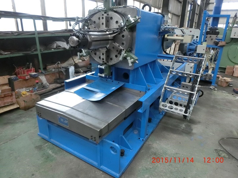
One end of the floating beam is installed with either shrinking or flaring molds while one end is connected to the piston rod of the main hydraulic cylinder.
Both ends are covered on the tension rod and guided by it as they move along with the main hydraulic cylinder. The floating beam also features a linear displacement sensor that directly displays the working stroke of the main hydraulic cylinder.
The maximum working pressure for this main hydraulic cylinder device is selected based on steel pipe specifications and includes pressure digital display functionality. The tension rod is hydraulically preloaded to connect both clamping devices with this main hydraulic cylinder device.
The working speed range for this main hydraulic cylinder: is 5-20mm/s (adjustable). Each host has two sets of clamping devices driven by separate hydraulic cylinders that securely clamp onto each steel pipe.
The hydraulic system includes a pressure regulating device allowing for adjustment in clamping force via proportional valve control based on specific characteristics exhibited by different types of steel pipes


1 clamping device, 2 clamping die, 3 shrinking die, 4 floating beam, 5 main hydraulic cylinder device, 6 passive support roller, 7 tension rod, 8 base
The CNC Pipe Sizing Machine Installation and Commissioning